
Designing a DC-DC Converter with the onsemi MC33063AVDR2G Switching Regulator
The design of an efficient and reliable DC-DC power supply is a cornerstone of modern electronics. For applications requiring a non-isolated switching converter, the onsemi MC33063AVDR2G stands out as a highly versatile and cost-effective monolithic switching regulator. This IC is capable of operation in buck, boost, and inverting topologies, making it an excellent choice for a wide range of projects where voltage conversion is necessary.
Key Features and Operating Principle
The MC33063AVDR2G integrates the primary building blocks of a switching regulator onto a single chip. Its core components include a temperature-compensated reference, a duty cycle controlled oscillator, a driver stage, and a high-current output switch capable of handling up to 1.5A. The device operates by switching an internal bipolar transistor at a fixed frequency, typically up to 100 kHz. The energy is stored in an external inductor during the "on" time and released to the load during the "off" time. The output voltage is regulated by pulse-width modulation (PWM), where the feedback pin monitors a resistor divider network connected to the output. This feedback loop adjusts the switch's duty cycle to maintain a constant output voltage despite variations in input voltage or load current.
Critical Design Considerations
A successful design hinges on the careful selection of external components.
Inductor Selection: The inductor is arguably the most critical component. Its value must be chosen to ensure continuous conduction mode (CCM) for most load conditions, which improves efficiency and reduces output ripple. The inductance value is calculated based on the desired output current, input/output voltages, and operating frequency.
Capacitor Selection: Low-ESR (Equivalent Series Resistance) capacitors are essential for stability and low output voltage ripple. A large electrolytic or tantalum capacitor is used at the output to smooth the voltage, while a small ceramic capacitor is placed near the IC's supply pins for decoupling.
Current Sensing and Limiting: An external sense resistor (Rsc) sets the peak switch current. This provides inherent short-circuit protection for the converter, a vital feature for robustness. The value of this resistor is calculated to trip the internal comparator at the desired current limit.
Compensation: For stability, a compensation capacitor (Cc) is connected from the comparator input/output pin to ground. This capacitor prevents the control loop from oscillating and ensures a stable output.
Design Process and Layout Guidelines
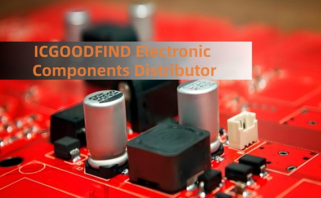
The design process typically begins with the topology selection (buck, boost, or inverting), followed by the calculation of component values using the formulas provided in the manufacturer's datasheet. Once the schematic is complete, the physical layout demands careful attention. Proper PCB layout is crucial for minimizing noise and ensuring stable operation. Key practices include:
Keeping the high-current paths (from the input capacitor, through the IC and inductor, to the output capacitor) as short and wide as possible.
Placing the feedback network away from noisy switching nodes to avoid injecting noise into the sensitive control loop.
Using a dedicated ground plane to provide a clean reference.
The onsemi MC33063AVDR2G remains a timeless and robust solution for DC-DC conversion. Its integrated design simplifies development, its flexibility supports multiple topologies, and its inherent protection features enhance reliability. For engineers and hobbyists alike, it provides a proven path to building efficient and cost-effective power supplies for a vast array of applications, from automotive systems to consumer electronics.
Keywords:
Switching Regulator
Pulse-Width Modulation (PWM)
Continuous Conduction Mode (CCM)
PCB Layout
Current Limiting

